Matrix Treadmill Models: Motor & Setup Walkthrough
Master the setup of Matrix treadmill models. This walkthrough covers motor horsepower requirements, electrical installation, and calibration.

Decoding Motor Size in Matrix Treadmill Models
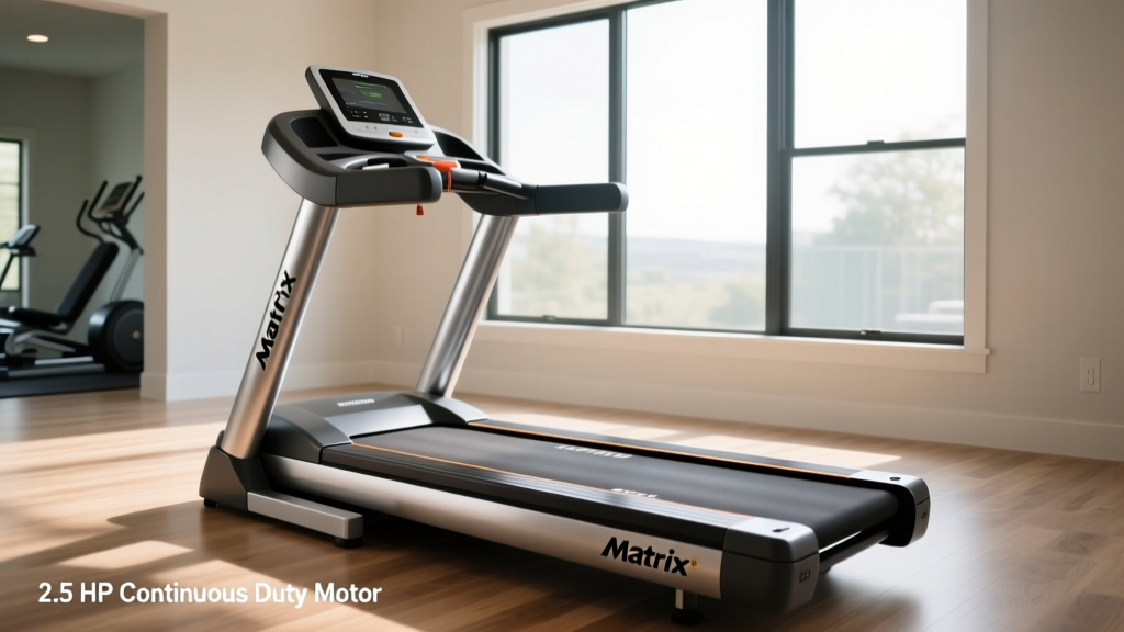
When investing in premium home gym equipment, understanding the heart of the machine—the motor—is non-negotiable. For 2026, Johnson Health Tech has refined the engineering behind their flagship matrix treadmill models, utilizing advanced Continuous Duty Horsepower (CHP) ratings that dictate not just performance, but your entire installation strategy. Unlike peak horsepower, which only measures a motor's maximum output for a fraction of a second, CHP measures the power the motor can sustain continuously during a grueling 10-mile run at a 12% incline.
Installing a high-CHP treadmill without preparing your home's infrastructure is a leading cause of premature motor failure and voided warranties. This comprehensive setup and installation walkthrough bridges the gap between motor specifications and physical assembly, ensuring your Matrix treadmill operates at factory-optimized efficiency from day one.
Quick Reference: Matrix Motor Specifications & Electrical Needs
| Model | Motor Type | CHP Rating | Circuit Requirement | Machine Weight |
|---|---|---|---|---|
| Matrix T7xe | AC Commercial | 4.0 CHP | 20-Amp Dedicated | 352 lbs |
| Matrix T5x | DC Heavy-Duty | 3.25 CHP | 15-Amp Dedicated | 305 lbs |
| Matrix TF50 | DC Standard | 3.0 CHP | 15-Amp Dedicated | 295 lbs |
Data sourced from Matrix Fitness official 2026 equipment specifications.
Phase 1: Electrical Preparation Based on Horsepower
The most critical installation step occurs before you even unbox the machine. High-horsepower motors, specifically the 4.0 CHP AC motor found in the Matrix T7xe, experience a massive 'inrush current' upon startup. This initial surge can draw up to 15 amps momentarily before settling into its continuous operating draw.
The 20-Amp Dedicated Circuit Rule
If you plug a 4.0 CHP Matrix treadmill into a shared 15-amp bedroom or basement circuit, the startup surge will likely trip the breaker, or worse, cause voltage drops that degrade the motor's internal windings over time. According to the National Electrical Code (NEC) guidelines for heavy appliances, a 20-amp dedicated circuit (NEMA 5-20R receptacle) is mandatory for commercial-grade 4.0 CHP motors.
- For 4.0 CHP Models (T7xe): Hire a licensed electrician to install a 20-amp dedicated line with 12-gauge wiring.
- For 3.0 - 3.25 CHP Models (T5x, TF50): A standard 15-amp dedicated circuit is sufficient, provided no other high-draw appliances (like space heaters or window AC units) share the breaker.
Expert Insight: Never use an extension cord or a surge protector with a high-CHP treadmill. Surge protectors can restrict the amperage flow during heavy incline intervals, causing the motor controller to overheat and throw an E02 error code. Plug the machine directly into the wall receptacle.
Phase 2: Physical Unboxing and Clearance Mapping
Matrix treadmill models are exceptionally heavy due to their oversized motor housings and reinforced steel frames. The T7xe weighs over 350 pounds. You will need two people and a furniture dolly to move the main chassis into position.
ASTM Safety Clearances
Before finalizing the placement, you must adhere to the safety clearances established by the ASTM International standards for motorized treadmills. Failing to leave adequate rear clearance is a severe safety hazard and can restrict the motor's cooling airflow.
- Rear Clearance: Leave a minimum of 78 inches (approx. 6.5 feet) of unobstructed space directly behind the treadmill. This allows the user to be safely ejected backward in the event of a fall while the motor continues to spin the belt.
- Side Clearance: Maintain at least 24 inches of clearance on both the left and right sides of the running deck for emergency dismounts and ventilation.
- Overhead Clearance: Measure the ceiling height. The Matrix T7xe's deck sits 9 inches off the ground, and at a 15% maximum incline, the rear of the deck elevates significantly. Ensure you have at least 12 inches of clearance above the tallest user's head at max incline.
Phase 3: Upright Assembly and Console Wiring
The uprights house the data cables that connect the console to the motor control board (MCB) located in the front motor hood. Damaging these wires during setup is a common installation failure.
- Align the Uprights: With one person supporting the left upright, align the bolt holes with the base frame. Use the included 15mm socket wrench to secure the four carriage bolts, but do not fully tighten them until both uprights are mounted.
- Connect the Data Cable: Locate the zip-tied wire harness inside the upright tube. Carefully connect the console data cable. Critical Step: Inspect the pin array. If a single pin is bent during connection, the console will not receive RPM data from the motor's optical sensor, resulting in an immediate E01 speed sensor error upon boot.
- Secure and Tighten: Route the excess cable into the tube, lower the console onto the uprights, secure the console bolts, and finally, torque the base upright bolts to 45 ft-lbs.
Phase 4: Deck Leveling and Motor Strain Prevention
A motor's lifespan is directly tied to the physical friction of the running belt. If your treadmill is not perfectly level, the belt will track to one side, creating severe edge friction. This friction forces the motor to draw excess amperage to maintain speed, mimicking the failure modes of a much smaller, underpowered motor.
The Leveling Procedure
- Place a 24-inch carpenter's level horizontally across the middle of the running deck.
- Adjust the two rear leveling feet (located under the rear endcaps) using a 17mm open-end wrench until the bubble is perfectly centered.
- Repeat the process vertically (front to back) to ensure the machine isn't rocking on its front transport wheels.
Belt Tension Calibration
Factory belt tension is often set for shipping, not running. Perform the 'Lift Test' to calibrate the belt to the motor's specific CHP output:
- Reach under the center of the running belt and lift upward.
- For the 4.0 CHP T7xe, you should be able to lift the belt exactly 2.5 to 3 inches off the deck.
- For the 3.0 CHP TF50, aim for 2 to 2.5 inches of lift.
- If the belt is too tight (less than 2 inches), use the provided 3/16-inch Allen wrench to turn both rear roller adjustment bolts counter-clockwise by exactly one-quarter turn. Over-tightening the belt is the number one cause of premature MCB failure in home setups.
Phase 5: Initial Power-On and Firmware Calibration
Once plugged into your dedicated circuit, power on the machine via the red rocker switch located on the front motor hood. Before your first run, you must run the internal motor calibration sequence to synchronize the console's software with the physical motor.
Matrix Motor Calibration Sequence
- Ensure the safety magnetic key is inserted into the console.
- Press and hold the INCLINE UP and SPEED DOWN buttons simultaneously for 3 to 5 seconds until the screen enters 'Engineering Mode'.
- Navigate to the 'Auto-Calibration' or 'Motor Test' submenu.
- Press Start. The treadmill will automatically cycle through speeds from 1.0 MPH to 12.0 MPH, and inclines from 0% to 15%, calibrating the internal potentiometers and optical sensors.
- Stand on the side rails during this process. Do not step on the belt while it is calibrating.
Common Post-Installation Motor Error Codes
If your setup encountered a hitch, the Matrix console will communicate the issue via specific error codes. Here is how to troubleshoot motor-related installation errors:
- E01 (Speed Sensor Error): The console is not receiving RPM data. Check the data cable connection in the upright. Alternatively, the optical sensor inside the motor hood may have been bumped during shipping and needs realignment with the motor flywheel.
- E02 (Over-Current / Motor Drive Error): The motor is drawing too many amps. This is almost always caused by an over-tightened running belt, a lack of silicone deck lubrication, or the machine being plugged into an inadequate 15-amp circuit that is suffering from voltage sag.
- E05 (Incline Motor Error): The incline actuator motor is not communicating. Verify that the incline motor wire harness is securely clicked into the main MCB under the front hood.
- [ ] Dedicated circuit verified with a multimeter (reading 115V-120V).
- [ ] 78-inch rear safety clearance established.
- [ ] Belt tension passes the 2.5-inch lift test.
- [ ] Auto-calibration sequence completed without interruption.
Final Walkthrough Checklist
Before committing to your first workout, verify the following installation milestones:
By respecting the relationship between motor horsepower, electrical infrastructure, and physical calibration, your Matrix treadmill will deliver a commercial-grade experience that rivals any high-end fitness club.
More gear to consider
All reviews
NordicTrack Treadmill 2.6 CHP Belt Lubrication & Care

Stop Feeling Like a Shrimp on Treadmills: 2026 Stair Climber Guide

Ava Addams Treadmill Trend: Folding Treadmill Maintenance & Reviews
Elliptical vs Treadmill Longevity: Beyond Feier Treadmill Reviews
Stair Climber Guide: Is It Harder to Run on a Treadmill or Outside?