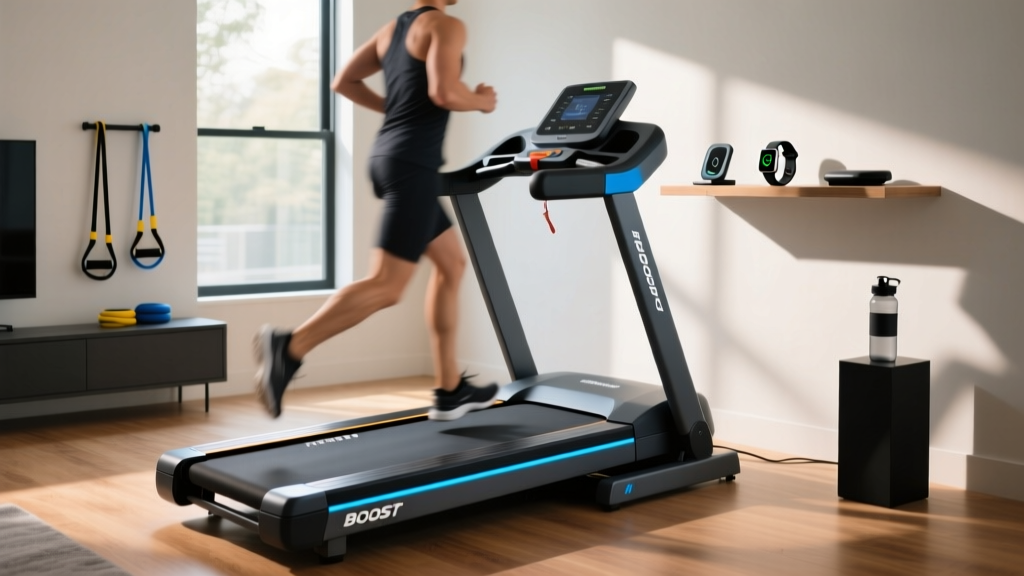
Boost Treadmills Setup: Motor Size and Horsepower Guide
Master your boost treadmills setup with our motor size and horsepower guide. Learn CHP ratings, electrical requirements, and installation steps.

The Heart of the Machine: Sizing Motors for Boost Treadmills
When unboxing and assembling high-performance cardio equipment, the physical frame often gets the most attention. However, for technicians and advanced home-gym builders, the true focal point of any setup is the drivetrain. Setting up commercial-grade or high-output residential boost treadmills requires a meticulous understanding of motor sizing, horsepower ratings, and electrical integration. A poorly matched or improperly installed motor will result in thermal shutoffs, degraded running belts, and ultimately, a fried lower control board.
In the modern fitness equipment landscape, manufacturers have largely transitioned to Brushless DC (BLDC) motors for premium models, offering superior torque at low speeds and significantly reduced maintenance compared to traditional brushed DC motors. But before you torque the first motor mount bolt, you must verify that the motor's horsepower aligns with your specific biomechanical and usage requirements.
Decoding Horsepower: Peak vs. Continuous Duty (CHP)
The most common trap consumers and novice installers fall into is confusing Peak Horsepower with Continuous Duty Horsepower (CHP). Peak HP measures the absolute maximum output the motor can achieve for a few seconds before the thermal overload switch trips. It is largely a marketing metric. CHP, on the other hand, measures the horsepower the motor can sustain indefinitely during a grueling workout without overheating.
⚠️ Critical Setup Warning: Never base your electrical circuit planning on Peak HP. Always calculate your amperage draw and wire gauge requirements using the CHP rating and the motor's voltage specification. Misjudging this can lead to melted 14 AWG wiring and severe fire hazards.Motor Sizing Matrix by User Profile
To ensure your boost treadmills setup is optimized for longevity, cross-reference the primary user's weight and intended workout intensity with the table below. Undersizing the motor forces the Pulse Width Modulation (PWM) controller to push maximum amperage constantly, generating excess heat.
| Usage Profile | Max User Weight | Minimum CHP Required | Recommended Motor Type | Flywheel Supplement |
|---|---|---|---|---|
| Walking / Light Jogging | Under 180 lbs | 2.5 CHP | Brushed DC | 12 lbs |
| Daily Running (3-5 hrs/wk) | Up to 250 lbs | 3.25 CHP | Brushed DC / BLDC | 15 lbs |
| Sprinting / HIIT / Heavy Use | 250 - 350 lbs | 4.0+ CHP | Brushless DC (BLDC) | 18+ lbs |
| Commercial / 24-7 Facility | Unrestricted | 5.0+ CHP (AC Motor) | 3-Phase AC | 25+ lbs |
Electrical Prerequisites: Avoiding the 15-Amp Trap
Before moving the treadmill chassis to its final location, you must verify the room's electrical infrastructure. A 4.0 CHP motor on a boost treadmill can draw between 14 and 18 amps under peak load (such as a heavy user accelerating from 0 to 10 MPH). Standard residential bedrooms and living rooms are typically wired with 15-amp breakers. If the treadmill shares this circuit with an HVAC unit, a space heater, or even a large television, the breaker will trip, or worse, the wiring inside the walls will overheat.
According to the National Fire Protection Association (NFPA 70: National Electrical Code), heavy-draw appliances require dedicated circuits. For any treadmill equipped with a 3.5 CHP motor or larger, you must install a dedicated 20-amp circuit with 12-gauge copper wiring and a 20-amp NEMA 5-20R receptacle. Do not use extension cords or surge protectors; plug the machine directly into the wall to prevent voltage drop, which starves the motor and causes the PWM controller to compensate by overworking the IGBT transistors.
Step-by-Step Motor & Drivetrain Installation Walkthrough
Once the electrical environment is secured, proceed with the physical setup. Proper installation of the motor and drivetrain components is critical to preventing harmonic vibration, which is the silent killer of lower control boards.
Phase 1: Chassis Leveling and Motor Mount Isolation
Place the treadmill frame on the floor and use a machinist's level across the side rails. Adjust the rear leveling feet until the bubble is perfectly centered, then lock the nuts. Next, locate the motor mount bracket. High-end boost treadmills utilize rubber isolation grommets between the motor base and the steel chassis. Do not skip these grommets. They absorb the low-frequency harmonic vibrations generated by the motor shaft. Without them, vibration transfers directly into the frame and eventually shakes the solder joints loose on the lower control board, leading to catastrophic electronic failure within 12 to 18 months.
Phase 2: Mounting the High-Torque Motor
Lower the motor into the mounting bracket. Insert the M10 hex bolts but do not fully tighten them yet. The motor must be able to pivot slightly on the tensioning bracket to allow for drive belt adjustment. Ensure the motor's cooling fan intake is facing away from the main chassis wall to allow for unobstructed airflow.
Phase 3: Drive Belt Alignment and Tensioning
Loop the poly-V drive belt around the motor pulley and the front roller pulley. This is where precision is mandatory. Pivot the motor outward on the tensioning bracket to apply pressure to the belt.
- The Deflection Test: Press down on the center of the drive belt with your thumb. You should achieve exactly 1/2 inch (12.7 mm) of deflection.
- Over-tensioning: If the belt is too tight (less than 1/4 inch deflection), it will place immense lateral stress on the motor's front bearing, leading to a high-pitched whining noise and eventual bearing seizure.
- Under-tensioning: If the belt is too loose, it will slip under heavy footfalls, causing a distinct burning rubber smell and erratic speed fluctuations.
Once the 1/2-inch deflection is achieved, torque the motor mount bolts to 35 ft-lbs using a calibrated torque wrench.
Wiring the PWM Controller Board
With the mechanical drivetrain secured, connect the motor to the lower control board. As noted by the repair experts at Treadmill Doctor, proper wiring and grounding are essential to prevent static discharge from destroying the board's microprocessors.
- Motor Leads: Connect the red (positive) and black (negative) motor leads to the corresponding M+ and M- terminals on the board. Apply a small amount of dielectric grease to the spade connectors to prevent oxidation over time.
- Optical Sensor / Tachometer: Align the optical sensor with the slotted disc on the motor flywheel. The gap must be exactly 2mm to 3mm. If the gap is too wide, the board will lose RPM readings and trigger an E1 speed error code.
- Grounding Strap: Attach the static grounding wire from the chassis to the designated ground screw on the motor mount. This bleeds off the static electricity generated by the friction of the running belt, protecting the sensitive PWM logic board.
The 30-Minute Break-In and Calibration Protocol
Do not immediately jump on the treadmill for a sprint. The motor brushes (if using a brushed DC motor) and the running belt require a break-in period to seat properly and distribute factory lubricants.
Expert Calibration Tip: Run the machine unweighted to allow the silicone belt lubricant to spread evenly across the phenolic deck. This reduces the coefficient of friction, directly lowering the amperage draw on the motor during the critical first hours of use.
Execute the following unweighted break-in cycle:
- Minutes 0-10: Set speed to 3.0 MPH. Listen for any rhythmic clicking from the drive belt or squealing from the roller bearings.
- Minutes 10-20: Increase speed to 6.0 MPH. Verify that the motor cooling fan is engaging and pushing air effectively.
- Minutes 20-30: Push the machine to its top speed (usually 12.0 MPH). Monitor the console for any flickering or sudden drops in the incline display, which would indicate a voltage sag from an inadequate electrical circuit.
Troubleshooting Edge Cases Post-Installation
Even with a flawless setup, high-output boost treadmills can present unique edge cases during the first week of use. Here is how to diagnose the two most common installation-related failures:
1. Thermal Overload Trips Mid-Run
If the motor suddenly stops and will not restart for 10-15 minutes, the internal thermal overload switch has tripped. This is rarely a defective motor; it is almost always an installation error. Check the belt tension. A belt that is too tight, or a running belt that lacks proper silicone lubrication, increases deck friction by up to 40%. The motor has to work significantly harder to overcome this friction, generating excess heat. Apply 100% pure silicone treadmill lubricant under the belt and re-test.
2. ESD (Electrostatic Discharge) Console Resets
If the console randomly resets or changes incline on its own while a user is running, you are experiencing ESD. The friction of shoes on the belt generates a massive static charge. If the grounding strap was omitted during Phase 3, or if the user is running on a high-pile carpet without an equipment mat, that static arcs into the console wiring. Ensure a dedicated equipment mat is placed under the treadmill, and verify the chassis-to-motor ground wire is securely fastened to bare metal.
Final Safety and Clearance Checks
Before considering the setup complete, verify the physical footprint. The U.S. Consumer Product Safety Commission (CPSC) strongly advises maintaining a minimum clearance of 24 inches on both sides of the treadmill and at least 78 inches (6.5 feet) directly behind the machine. In the event of a fall or an emergency stop, this clearance zone prevents the user from being pinned against a wall or furniture by the momentum of the running belt. Proper motor sizing, rigorous electrical preparation, and precise mechanical installation are the pillars of a safe, high-performance boost treadmill setup that will endure years of heavy use.
More gear to consider
All reviews
LifePro Pacer Folding Treadmill Belt Maintenance Guide

How to Start ProForm Treadmill & Maintain All Stationary Bike Types
Noise Level Comparison: Is a Portable Moves Treadmill the Quietest?

NordicTrack 900 Treadmill Belt Maintenance Trends 2026

Is Running on the Treadmill the Same as Running Outside? 2026 Guide
